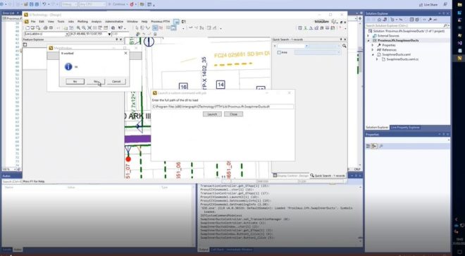
Shortening CustomCommand development time by using a proxy

One of the most time-consuming processes when developing with Hexagon G/Technology is creating custom commands. The usual development approach consists of the following iterative process:

  • Compile custom command
  • Launch G/Technology
  • Test custom command
  • Exit G/Technology
  • Modify custom command
During testing, only limited changes to the source code are allowed by the Visual Studio Edit and Continue function, effectively requiring multiple iterations of this sequence.

The process of starting and closing G/Technology can easiliy takeup multiple minutes and you need to close it because G/Technology will lock any assemblies containing your custom commands.

Customcommands are written in DotNet and therefore run in something called an “Assembly Domain”, in this case the G/Technology Assembly Domain. When you create a custom command loading other custom commands in its own assembly domain, dotnet will not load the same assembly again in fact creating a proxy. The following code snippet demonstrates this:

string assembly = @"c:\Program Files (86)\Intergraph\GTechnology\YourCustomCommand.dll";
byte[] assemblyBytes = File.ReadAllBytes(assembly);
System.Reflection.Assembly assemblyToLoad = Assembly.Load(assemblyBytes);

Type entryClass = assemblyToLoad.GetTypes().FirstOrDefault(t ⇒ typeof(IGTCustomCommandModal).IsAssignableFrom(t));
if( entryClass != null)
{
    IGTCustomCommandModal CCModal = (IGTCustomCommandModal)assemblyToLoad.CreateInstance(entryClass.FullName);
    CCModal.Activate();
    return;
}

entryClass = assemblyToLoad.GetTypes().FirstOrDefault(t ⇒ typeof(IGTCustomCommandModeless).IsAssignableFrom(t));
if( entryClass != null)
{
    IGTCustomCommandModeless CCModeless = (IGTCustomCommandModeless)assemblyToLoad.CreateInstance(entryClass.FullName);
    CCModeless.Activate(_customCommandHelper);
    return;
}

This snippet scans an assembly for a type implementing either interface ‘IGTCustomCommandModal‘ or ‘IGTCustomCommandModeless‘, which both can be found in namespace ‘Intergraph.GTechnology.Interfaces‘ and are needed to implement customcommands. If a type implements one of these interfaces, the proxy customcommand creates an instance of it loading it in the assembly domain.

When this approach is used to load custom commands, G/Technology will not lock the containing assemblies after closing the custom command, enabling much shorter development cycles.

The technique constists of 2 or more custom commands, the first one being the proxy, the second one being the custom command to be developed. Once the first customcommand is started, it will show a dialog where the assembly containing the custom command to be developed should be entered :

Proxy dialog

Some extra querying to the G3E_CUSTOMCOMMAND table allows to provide useful metadata as shown in the pop-up window.

Then attach the Visual Studio debugger and press ‘Launch’ and any breakpoint in your customcommand should be hit and it can be tested. Once done, detach the debugger, modify code, compile and attach again, etc., etc. :

Debugging session active

An example of a session using this technique this can be seen in this this youtube video, showing a debug session of a custom command called “Swap Inner Ducts” which will just show a dialog and a messagebox, but the important part is that the customcommand is changed, recompiled and executed again using the Visual Studio debugger without leaving G/Technology.

Youtube video

Sources can be downloaded from here.

Credits go to Jan Stuckens for initially coming up with this idea.

Thanks to Michaël Demanet and Didier de Bisschop from Proximus for use of their environment to test this technique.

Notes :

  • the proxy needs to be built with debugging information, else breakpoints in the target customcommand won’t be hit
  • All referenced assemblies need to be loaded
  • This technique has been used with assemblies containing a single custom command, assemblies with multiple custom commands where not tested
  • G/Technology version 10.04.2002.00035 was used to test this approach

Workaround for the Dotnet Maui Tabs ‘OnAppearing’ event

Tabs in dotnet maui have an ‘OnAppearing’ event which you would expect to be called each time a tab is activated. This however is not the case and a possible workaround is to initialize data in a static manner and pass arguments using the ‘Arguments’-construct like shown in this post :

Tab1:

<!--?xml version="1.0" encoding="utf-8" ?-->
<contentpage xmlns="http://schemas.microsoft.com/dotnet/2021/maui" xmlns:x="http://schemas.microsoft.com/winfx/2009/xaml" x:class="MauiApp1.Pages.Tab1" xmlns:local="clr-namespace:MauiApp1.Data" title="Tab1">

	<contentpage.bindingcontext>
		<local:itemviewmodel>
			<x:arguments>
				<x:int32>10</x:int32>
			</x:arguments>
		</local:itemviewmodel>
	</contentpage.bindingcontext>

	<verticalstacklayout>
		<label text="Integers as argument">
		<collectionview x:name="collectionView" margin="5" itemtemplate="{StaticResource DataTemplate1}" itemssource="{Binding ItemCollection}" selectionmode="Single">
	</collectionview></label></verticalstacklayout>

</contentpage>

Tab2:

<!--?xml version="1.0" encoding="utf-8" ?-->
<contentpage xmlns="http://schemas.microsoft.com/dotnet/2021/maui" xmlns:x="http://schemas.microsoft.com/winfx/2009/xaml" x:class="MauiApp1.Pages.Tab2" xmlns:local="clr-namespace:MauiApp1.Data" title="Tab2">

	<contentpage.bindingcontext>
		<local:itemviewmodel>
			<x:arguments>
				<x:int32>20</x:int32>
			</x:arguments>
		</local:itemviewmodel>
	</contentpage.bindingcontext>

	<verticalstacklayout>
		<label text="Integers as argument">
		<collectionview x:name="collectionView" margin="5" itemtemplate="{StaticResource DataTemplate1}" itemssource="{Binding ItemCollection}" selectionmode="Single">
	</collectionview></label></verticalstacklayout>

</contentpage>

Tab3:

<!--?xml version="1.0" encoding="utf-8" ?-->
<contentpage xmlns="http://schemas.microsoft.com/dotnet/2021/maui" xmlns:x="http://schemas.microsoft.com/winfx/2009/xaml" x:class="MauiApp1.Pages.Tab3" xmlns:local="clr-namespace:MauiApp1.Data" title="Array of integers">

	<contentpage.bindingcontext>
		<local:itemviewmodel>
			<x:arguments>
				<x:array type="{x:Type x:Int32}">
					<x:int32>10</x:int32>
					<x:int32>11</x:int32>
					<x:int32>12</x:int32>
					<x:int32>13</x:int32>
					<x:int32>14</x:int32>
					<x:int32>15</x:int32>
				</x:array>
			</x:arguments>
		</local:itemviewmodel>
	</contentpage.bindingcontext>

	<verticalstacklayout>
		<label text="Array of integers as arguments">
		<collectionview x:name="collectionView" margin="5" itemtemplate="{StaticResource DataTemplate1}" itemssource="{Binding ItemCollection}" selectionmode="Single">
	</collectionview></label></verticalstacklayout>

</contentpage>

Where the Itemcollection looks like this:

public class ItemViewModel : INotifyPropertyChanged
{
	public ItemViewModel( )	{}

	public ItemViewModel( int categoryId)
	{
		this.ItemCollection = new ObservableCollection<item>( );

		for( int i = 0; i ‹ 4; i++)
		{
			this.ItemCollection.Add( new Item( ) { Name = $"V1-{categoryId}", Description = $"c{categoryId}/T1 rocks"});
		}
	}

	public ItemViewModel( int[] categoryIds)
	{
		this.ItemCollection = new ObservableCollection<item>( );

		for( int i = 0; i ‹ categoryIds.Length; i++ )
		{
			int categoryId = categoryIds[i];
			this.ItemCollection.Add( new Item( ) { Name = $"V1-{categoryId}", Description = $"c{categoryId}/T1 rocks"});
		}
	}

	public event PropertyChangedEventHandler PropertyChanged;

	protected virtual void OnPropertyChanged(PropertyChangedEventArgs e)
	{		
		ArgumentNullException.ThrowIfNull(e);
		PropertyChanged?.Invoke(this, e);
	}

	public ObservableCollection<item> ItemCollection	{ get; set; }
}

This will result in a nice flexible way of initialisation for tabs:

Integer argument
Integer argument
Array of integers as argument

An example project can be loaded from here.

A Multilevel Responsive Blazor-menu

When you generate a Blazor-server app or Webassembly the standard template generates a menu docked to the left which is responsive, but has some drawbacks :

  • It doesn’t support multiple levels
  • It depends on bootstrap which introduces additional complexity
  • Menu-items are hardcoded

Webapplications need a flexible way enabling multilevel-, responsive menus, the standard template is not flexible enough for this purpose, this post describes a solution to this problem. The approach taken consists of the following parts :

  1. A Component ‘ResponsiveMenuComponent’
  2. A stylesheet ‘menu.css’
  3. JQuery functions to toggle menus

Suppose our requirement is to generate a menu whos structure comes from an external source and simulates a webshop, the menustructure looks like this :

Home
Jeans -> Wide leg jeans
Jeans -> Straight jeans
Jeans -> Loose jeans
Shorts -> Sweet jersey shorts -> Jersey1
Shorts -> Sweet jersey shorts -> Jersey2
Shorts -> Denim shorts
Skirts
Blazors

The ResponsiveMenu-component has a property ‘MenuEntryCollection’ which is used to render the menu. With the ResponsiveMenu-component in place, the following creates the required menu-structure :

MainLayout.razor :

<ResponsiveMenuComponent Items=@Items />

@code {
public MenuEntryCollection	Items = new MenuEntryCollection( )
	{
	new MenuEntry( ) { Text = "Home",		Url = "/" }
,	new MenuEntry( ) { Text = "Jeans",		Url = "/jeans" 
	, SubItems = new MenuEntryCollection( )
		{
		new MenuEntry( ) { Text = "Wide leg jeans",	Url = "/wide_leg_jeans" }
	,	new MenuEntry( ) { Text = "Straight jeans",	Url = "/straight_jeans" }
	,	new MenuEntry( ) { Text = "Loose jeans",	Url = "/loose_jeans" }
}
}
,	new MenuEntry( ) { Text = "Shorts",		Url = "/shorts" 
	, SubItems = new MenuEntryCollection( )
		{
		new MenuEntry( ) { Text = "Sweet jersey shorts",	Url = "/sweet_jersey" 
		, SubItems = new MenuEntryCollection( )
			{
			new MenuEntry( ) { Text = "Jersey1",	Url = "/Jersey1" }
		,	new MenuEntry( ) { Text = "Jersey2",	Url = "/Jersey2" }
	}
	}
	,	new MenuEntry( ) { Text = "Denim shorts",			Url = "/demin_jersey" 	}
}
}
,	new MenuEntry( ) { Text = "Skirts",		Url = "/skirts" }
,	new MenuEntry( ) { Text = "Blazers",	Url = "/blazers" }
};
}

The ‘MenuEntryCollection’ and ‘MenuEntry’-classes:

public class MenuEntryCollection : System.Collections.Generic.List<MenuEntry>{ }

public class MenuEntry
{
	internal string Text { get; set; }
	internal string Url  { get; set; }

	internal MenuEntryCollection SubItems{ get; set; }
}

When the website is rendered for non-mobile devices, multilevel-items are expanded by css included in ‘menu.css’. Before blazor, if a user would select an item in the menu a postback would occur rebuilding the menu, in Blazor this is not the case causing the selected menu-item to be expanded. In a regular blazor app, it is collapsed using css switched when a user clicks a div, the ‘@onclick=”ToggleNavMenu’ construct. Doing this for a menu whos structure is unknown in advance would be very convenient, therefore this is done using jQuery declared inside _Host.cshtml together with some other needed functions:

<script type="text/javascript">
window.onBlazorReady = function() {
	$('.top-menu').not(".mobile").click(function () {
		$(this).find('ul > li').toggle();
	});

	$('.top-menu').not(".mobile").hover(function () {
		$(this).find('ul > li').show();
	}, function() {});

	$('.menu-toggle').click(function () {
		$(this).siblings('.top-menu.mobile').slideToggle('slow');
	});

	$('.top-menu.mobile .sublist-toggle').click(function () {
		$(this).siblings('.sublist').slideToggle('slow');
	});

	$('.top-menu.mobile .sf-with-ul').click(function () {
		$(this).siblings('.sublist').slideToggle('slow');
	});

	$('.top-menu.mobile li:not(:has(ul))').click(function () {
		$(this).closest('.top-menu.mobile').toggle();
	});
};
</script>

The ‘onBlazorReady’-function is called inside the ‘OnAfterRenderAsync’ inside ‘ResponsiveMenuComponent.razor’:

protected override Task OnAfterRenderAsync( bool firstRender )
{
  if( firstRender)
  {
    ValueTask valueTask = JsRuntime.InvokeVoidAsync("onBlazorReady");
  }

  return base.OnAfterRenderAsync( firstRender );
}

A running website using this component can be seen here, sources can be downloaded from github.

Notes:

  • The menu in component ResponsiveMenuComponent is generated in codebehind which disables css-isolation
  • The example given is Blazor-server but can also be used for Blazor-WASM
  • Menu items for the desktop are collapsed on hover using css, but there is no such thing as ‘hover’ on mobile devices. Because of this, we need two separate menus mobile and desktop

Invoking Oracle Spatial from a Custom Command

Consider a requirement where the centroid of a set of points needs to be retrieved within a custom command. This can be achieved using the ‘GTDataProvider.DataContext.Execute‘-method:

IGTApplication GTApp = GTClassFactory.Create<IGTApplication>( );

string coors = "0, 0, 0, 10, 0, 0, 10, 10, 0, 0, 10, 0, 0, 0, 0"; // change to actual coordinates
string sql = $@"WITH shape AS
  ( 
  	select 1 id, sdo_geometry( 3003, NULL, NULL
         , sdo_elem_info_array( 1, 1003, 1)
         , sdo_ordinate_array({coors} )) G FROM dual
  )
SELECT s.ID, t.x, t.y FROM shape S, sdo_util.getvertices( sdo_geom.sdo_centroid( S.G)) t";

ADODB.Recordset rs = GTApp.DataContext.Execute( sql, out _, (int)ADODB.CommandTypeEnum.adCmdText);

if( rs == null) return;
if( rs.RecordCount == 0 ) return;
rs.MoveFirst( );

string x = System.Convert.ToString( rs.Fields[ "X"].Value);
string y = System.Convert.ToString( rs.Fields[ "Y"].Value);

System.Diagnostics.Debug.WriteLine( string.Format( "x={0}, y={1}", x, y)); // x=5, y=5

rs.Close();
rs = null;

Rubberbanding in G/Technology

Whenever a user is digitizing a polygon, he expects feedback when moving the cursor before actually adding a point, the system should ‘rubberband’ the position under the cursor and only add it to a collection of points after the user left-mouse clicks in the Window. Key to rubberbending in G/Technology is responding to three events :

  1. CustomCommandHelper_Click
  2. CustomCommandHelper_MouseMove
  3. CustomCommandHelper_DblClick

CustomCommandHelper_Click

private void CustomCommandHelper_Click( object sender, GTMouseEventArgs e )
{
  if( this.PntCnt == 0)
  {
    this.PntCnt++;

    this.Idx = this.GeometryCreationService.AddGeometry( GTClassFactory.Create<IGTPolygonGeometry>(), StyleId);
    this.GeometryCreationService.AppendPoint( this.Idx, e.WorldPoint);
    return;
  }

  this.GeometryCreationService.AppendPoint( this.Idx, e.WorldPoint);
}

CustomCommandHelper_MouseMove

private void CustomCommandHelper_MouseMove( object sender, GTMouseEventArgs e )
{
  if( this.PntCnt == 0)
  {
    this.setGtStatusBar( "Click to start digitizing");
    return;
  }

  if( this.PntCnt == 1)
  {
    this.setGtStatusBar( "Click to add point");
    this.GeometryCreationService.SetDynamicPoint( this.Idx, e.WorldPoint);
    return;
  }
				
  this.setGtStatusBar( "Click to add point, Doubleclick to end");
  this.GeometryCreationService.SetDynamicPoint( this.Idx, e.WorldPoint);
}

CustomCommandHelper_DblClick

private void CustomCommandHelper_DblClick( object sender, GTMouseEventArgs e )
{
  this.PntCnt = 0;
}

Besides these 3 events, the following general code is used:

general code

private IGTApplication _GTApp = null;
private IGTApplication GTApp
{
  get
  {
    if( this._GTApp == null)
    {
      this._GTApp = GTClassFactory.Create<IGTApplication>();
    }

    return( this._GTApp);
   }
}

private IGTGeometryCreationService GeometryCreationService { get; set; } = GTClassFactory.Create<IGTGeometryCreationService>();

private void setGtStatusBar( string message)
{
  this.GTApp.SetStatusBarText( GTStatusPanelConstants.gtaspcMessage, message);
}

private int Idx { get; set; }
private const int StyleId = 5010;

The complete code can be downloaded from here.

Specialized ViewComponents

Suppose you want to introduce an inheritance chain in ASP.Net Core to use some businesslogic in a baseclass :

namespace Foo.Core.Web
{
	using Microsoft.AspNetCore.Mvc;
	using System.Collections.Generic;

	public class CoolBaseViewComponentDetail : ViewComponent
	{
		protected List<string> getItems(int itemCount)
		{
			List<string> items = new List<string>();
			for (int i = 0; i < itemCount; i++)
			{
			  items.Add(string.Format("string {0}", i));
			}

			return (items);
		}
	}
 
	public class SpecializedViewComponentDetail : CoolBaseViewComponentDetail
	{
		public virtual IViewComponentResult Invoke(int numberOfItems)
		{
			List<string> items = getItems(numberOfItems);
			return (View(viewName: "~/Src/ViewComponentSpecialized.Detail.cshtml", model: items));
		}
	}
}

ViewComponentSpecialized.Detail renders like this :

@model System.Collections.Generic.List<string>
<ul>
    @foreach( string item in Model)
    {
        <li>@item</li>
    }
</ul>

If you invoke this viewcomponent you get an exception :

@await Component.InvokeAsync( name:"SpecializedViewComponentDetail", arguments:new { numberOfItems = 3 } )

InvalidOperationException: Could not find an 'Invoke' or 'InvokeAsync' method for the view component 'Foo.Core.Web.CoolBaseViewComponentDetail'.

ASP.Net core requires an ‘Invoke’-method on every ViewComponent-specialized class, even if it is not directly called. Solution is to introduce this method but to let it throw an exception when directly called:

namespace Foo.Core.Web
{
	using Microsoft.AspNetCore.Mvc;
	using System.Collections.Generic;
		
	public class CoolBaseViewComponentDetail : ViewComponent
	{
		public virtual IViewComponentResult Invoke(int numberOfItems)
		{
			throw new System.NotSupportedException("Specialized classes should implement this");
		}

		protected List<string> getItems(int itemCount)
		{
			List<string> items = new List<string>();
			for (int i = 0; i < itemCount; i++)
			{
			  items.Add(string.Format("string {0}", i));
			}

			return (items);
		}
	}
 
	public class SpecializedViewComponentDetail : CoolBaseViewComponentDetail
	{
		public virtual IViewComponentResult Invoke(int numberOfItems)
		{
			List<string> items = getItems(numberOfItems);
			return (View(viewName: "~/Src/ViewComponentSpecialized.Detail.cshtml", model: items));
		}
	}
}

Now the view renders:

o string 0
o string 1
o string 2

cheers, Stephan

Configuring Webservice endpoints in a .Net Core Webapplication

If you need to invoke a WCF-Soap compliant Webservice from an ASP.Net application, the endpoints for it are stored in the Web.Config:

<client>
    <bindings>
      <basicHttpBinding>
        <binding name="BasicHttpBinding_IService1" />
        <binding name="BasicHttpsBinding_IService1">
          <security mode="Transport" />
        </binding>
        <binding name="BasicHttpBinding_IService11" />
        <binding name="BasicHttpsBinding_IService11">
          <security mode="Transport" />
        </binding>
      </basicHttpBinding>
    </bindings>

  <endpoint address="http://sdeservice.azurewebsites.net/Service1.svc"
            binding="basicHttpBinding"
            bindingConfiguration="BasicHttpBinding_IService1"
            contract="ServiceReference1.IService1" 
            name="BasicHttpBinding_IService1" />

  <endpoint address="https://sdeservice.azurewebsites.net/Service1.svc"
            binding="basicHttpBinding"
            bindingConfiguration="BasicHttpsBinding_IService11"
            contract="ServiceReference2.IService1" 
            name="BasicHttpsBinding_IService1" />
/client>

If you need to invoke the same Webservice from an ASP.Net Core application, there is no Web.Config and you need to store the endpoints in an applicationSettings.json file. The following applicationSettings.json file introduces a section 'Service1' with some properties defining the Webservice to use:

{
  "Logging": {
    "LogLevel": {
      "Default": "Information",
      "Microsoft": "Warning",
      "Microsoft.Hosting.Lifetime": "Information"
    }
  },
  "Service1": {
    "Title": "Service1",
    "Name": "Very Cool Webservice",
    "Endpoint": "http://sdeservice.azurewebsites.net/Service1.svc",
    "SecureEndpoint": "https://sdeservice.azurewebsites.net/Service1.svc"
  },
  "AllowedHosts": "*"
}

There are a couple of ways to get this configuration in .Net Core 3.1 :

  1. Bind configuration in controller
  2. Bind configuration in Startup
  3. Dynamically read configuration

Bind configuration in controller

Any .Net Core application allows you to bind a configuration to a simple POCO-class, the following code binds an instance of class 'Service1Config' to properties 'Title', 'Name', 'Endpoint' and 'SecureEndpoint' from the 'Service1'-section. Your controller needs to have a constructor with an 'IConfiguration'-argument, ASP.Net Core will invoke it and you can use it to bind to a class. Then the endpoint as stored in the 'Endpoint'-attribute can be used at the endpoint of a Webservice-client as shown in the ‘Invoke’-method or ‘InvokeSecure’ to use https:

public class HomeController : Controller
{
  private Service1Config ConfigClass { get; set; }

  public HomeController( IConfiguration configuration)
  {
    this.ConfigClass = new Service1Config( );
    IConfigurationSection section = configuration.GetSection( "Service1");
    section.Bind( this.ConfigClass);
  }

  public IActionResult Invoke()
  {
    ServiceReference1.Service1Client client = new ServiceReference1.Service1Client( Service1Client.EndpointConfiguration.BasicHttpBinding_IService1);
    string endpoint = this.ConfigClass.Endpoint;
    client.Endpoint.Address = new EndpointAddress( endpoint);
    string result = this.Client.GetData( 3);
    return( View( ));
  }

  public IActionResult InvokeSecure()
  {
    ServiceReference1.Service1Client secureClient = new ServiceReference1.Service1Client( Service1Client.EndpointConfiguration.BasicHttpsBinding_IService1);
    string secureEndpoint = this.ConfigClass.SecureEndpoint;
    secureClient.Endpoint.Address = new EndpointAddress( secureEndpoint);
    string result = this.Client.GetData( 3);
    return( View( ));
  }
}

public class Service1Config
{
  public string Title		  { get; set; }
  public string Name		  { get; set; }
  public string Endpoint	  { get; set; }
  public string SecureEndpoint{ get; set; }
}

Bind configuration in Startup

When you need to have access to the configuration globally, you can do the same in your programs 'Startup.cs':

public class Startup
{
  internal Service1Config ConfigClass{ get; set; }

  public Startup( IConfiguration configuration)
  {
    this.ConfigClass= new Service1Config( );
    IConfigurationSection section = configuration.GetSection( "Service1");
    section.Bind( this.ConfigClass);
  }
}

Dynamically read configuration

If you need to dynamically read the same configuration, you can do so like this :

public class HomeController : Controller
{
  public IActionResult Index()
  {		
    string title = new ConfigurationBuilder().AddJsonFile("appsettings.json").Build().GetSection("Service1")[ "Title"];
    string title = new ConfigurationBuilder().AddJsonFile("appsettings.json").Build().GetSection("Service1")[ "Title"];
    string endpoint = new ConfigurationBuilder().AddJsonFile("appsettings.json").Build().GetSection("Service1")[ "Endpoint"];
    string secureEndpoint = new ConfigurationBuilder().AddJsonFile("appsettings.json").Build().GetSection("Service1")[ "SecureEndpoint"];
    return( View( ));
  }
}

Notes

  • If you add a reference to a Webservice, Visual Studio 2019 will add a 'connectedServices.json' file which also appears when you publish suggesting it stores a reference to the endpoint url used by a webservice-client. This is not the case, and the file can be safely removed from the publish.
  • If you generate a proxy for http, the generated proxy will contain a constructor without arguments
  • If you generate a proxy for http and https (examples are using that), the generated proxy will contain a constructor with an argument indicating the protocol to use, either http or https (BasicHttpBinding_IService1/BasicHttpsBinding_IService1)

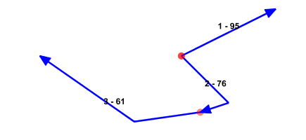
Sorting and merging geometries in Oracle Spatial

sample_set7

Consider a requirement where an unsorted set of geometries needs to be merged into a single geometry. Take for instance the following set of geometries where:

  • a Red dot indicates the startpoint
  • The arrow indicates the drawing direction
  • The label “1-50” indicates the order of drawing and an identifier for the geometry

Sample set 1

Sample set 1

Sample set 2

Sample set 2

Both of these geometries should be merged into the following:

Result set 1

Result set 1

Oracle lets you create your own aggregate function enabling a nice flexible solution, let’s try to create an aggregate function SDE_MERGE enabling us to create a 3002-gtype geometry or in G/Technology terms a ‘CompositePolylineGeometry’, (G3E_COMPONENT.G3E_TYPE=4). Our aggregate function must be able to:

    • Change the order of geometries. The order in which the geometries are drawn may not be the order in which the geometries need to be merged to create the resulting geometry.
    • Change direction of a geometry. Geometries may have different drawing directions, but when appending geometries to each other to create a resulting geometry, the direction needs to be the same.
    • Detect not supported situations:
      1. A closed set of Geometries
      2. Geometries with multiple connections
      3. A set of disjoint geometries

The picture below shows a closed set of Geometries, this set of geometry cannot be merged into a 3002-gtype geometry so when this situation is encountered SDE_MERGE should return null:

Closed set

Closed set

Also, if there are more then 2 geometries connecting to each other, no 3002-gtype geometry can be created:

Multiple connections

Multiple connections

When a set of geometries is not connected/disjoint, null should be returned:

Disjoint set

Disjoint set

Here’s the header of the SDO_MERGE function:

create or replace type SDE_MERGE_i as object
(
geom 	mdsys.sdo_geometry,

STATIC FUNCTION ODCIAggregateInitialize
( sctx IN OUT SDE_MERGE_i
) RETURN number,

MEMBER FUNCTION ODCIAggregateIterate
(   self IN OUT SDE_MERGE_i
, item IN mdsys.sdo_geometry
)	RETURN number,

MEMBER FUNCTION ODCIAggregateTerminate
(   self IN 	  SDE_MERGE_i
, ret  OUT    mdsys.sdo_geometry
, flgs IN     number
) RETURN number,

MEMBER FUNCTION ODCIAggregateMerge
(   self IN OUT SDE_MERGE_i
, ctx2 IN     SDE_MERGE_i
) RETURN number
);

Our SDE_MERGE function has a single member geom, a geometry which we will use to store all geometries to be merged and return the resulting geometry. When SDE_MERGE is called, Oracle first calls 'ODCIAggregateInitialize', this is were the initial geometry is initialized. Then, for each geometry in the applied order, 'ODCIAggregateIterate' is called and when all geometries have been entered, Oracle will call 'ODCIAggregateTerminate'. Sorting and merging geometries can only take place after all geometries are known so this is where the actual sorting and merging of geometries is done. Before this is called, we need some kind of data structure to store all geometries to be processed later. This is were a 3006-gtype geometry comes in, we will store all temporary geometries in it and enumerate this 3006-geometry when we need to do the sorting and merging.

This is all we need in 'ODCIAggregateIterate':

MEMBER FUNCTION ODCIAggregateIterate
(
self IN OUT SDO_MERGE_i
, item IN 	mdsys.sdo_geometry
) return number
IS
BEGIN
if( self.geom.SDO_ORDINATES is null)
then
SELF.geom := item;
return( ODCIConst.Success);
end if;

SELF.geom := sdo_util.append ( SELF.geom, item);
return( ODCIConst.Success);
END;

When all items are encountered Oracle calls the ‘ODCIAggregateTerminate’-function where the temporary 3006-gtype/multi-line geometry is enumerated, all 3002-gtype geometries in it are sorted and merged into a 3002-gtype geometry.

Implementation

The real work of this solution is done in the 'ODCIAggregateTerminate'-function where all the geometries in the temporary 3006-gtype geometry are enumerated to see if they can be merged into a single geometry. If they can, the order and direction of all the geometries is changed where needed, and then merged into a single geometry. The complete solution can be downloaded from here.

Testing

While the actual target data is G/Technology driven, I will use a table DB_ORIGIN_PATHS for testing purposes :

CREATE TABLE DB_ORIGIN_PATHS
(
ID          NUMBER,
PATH_FID    NUMBER(10),
HASH        INTEGER,
GEOM        MDSYS.SDO_GEOMETRY,
GEOM2D      MDSYS.SDO_GEOMETRY
);

The geometries are rendered using Geoserver/Openlayers so I can quickly inspect results without the hassle of publishing data with G/Technology. Each geometry inserted is converted to a 2D-geometry because Geoserver has problems rendering 3D-arcs, this 2D-geometry then is used to inspect the results:

CREATE OR REPLACE TRIGGER DB_ORIGIN_PATHS_AfterIU BEFORE INSERT or UPDATE ON DB_ORIGIN_PATHS
for each row
begin
:new.geom2d := SDO_CS.MAKE_2D( :new.GEOM);
end;
/

Furthermore, because I don’t have a reference to a fid of the applied geometries inside my 'SDE_MERGE'-implementation, I need some way of identifying the geometries. That’s why I introduced a ‘Hash’-value for each one :

create or replace function GETHASHCODE( theGeom mdsys.sdo_geometry)
return int
as
p1 		mdsys.sdo_geometry;
p2 		mdsys.sdo_geometry;
hash	int;
begin
p1 := SDO_LRS.GEOM_SEGMENT_START_PT( theGeom);
p2 := SDO_LRS.GEOM_SEGMENT_END_PT  ( theGeom);

hash := p1.sdo_ordinates( 1) + p1.sdo_ordinates( 2) + p2.sdo_ordinates( 1) + p2.sdo_ordinates( 2);
return( hash);
end;

Now onto our first testset, 3 basic lines :

BEGIN
delete from DB_ORIGIN_PATHS;

insert into DB_ORIGIN_PATHS( id, path_fid, geom)
select 1, 1, SDO_GEOMETRY( 3002, NULL, NULL,
SDO_ELEM_INFO_ARRAY( 1,2,1),
SDO_ORDINATE_ARRAY( 10,10,0, 20,10,0 ))
from dual;

insert into DB_ORIGIN_PATHS( id, path_fid, geom)
select 2, 2, SDO_GEOMETRY( 3002, NULL, NULL,
SDO_ELEM_INFO_ARRAY( 1,2,1),
SDO_ORDINATE_ARRAY( 20,10,0, 30,10,0))
from dual;

insert into DB_ORIGIN_PATHS( id, path_fid, geom)
select 3, 3, SDO_GEOMETRY( 3002, NULL, NULL,
SDO_ELEM_INFO_ARRAY( 1,2,1),
SDO_ORDINATE_ARRAY( 30,10,0, 40,10,0))
from dual;

update DB_ORIGIN_PATHS set hash = GETHASHCODE( geom);
commit;
END;

This renders into this :

Test set 1

Test set 1

Merging the geometries and deleting the old ones:

BEGIN
insert into DB_ORIGIN_PATHS( id, path_fid, geom)
select 100, 100, SDE_MERGE( geom) from rr.DB_ORIGIN_PATHS;

update DB_ORIGIN_PATHS set hash = GETHASHCODE( geom);
delete from DB_ORIGIN_PATHS where id < 100;
commit;
END;

Renders into:

Result set 1

Result set 1

Our second test set :

BEGIN
delete from DB_ORIGIN_PATHS;

insert into DB_ORIGIN_PATHS( id, path_fid, geom)
select 1, 1, SDO_GEOMETRY( 3002, NULL, NULL,
SDO_ELEM_INFO_ARRAY( 1,2,1),
SDO_ORDINATE_ARRAY( 10,10,0, 20,10,0 ))
from dual;

insert into DB_ORIGIN_PATHS( id, path_fid, geom)
select 2, 2, SDO_GEOMETRY( 3002, NULL, NULL,
SDO_ELEM_INFO_ARRAY( 1,2,1),
SDO_ORDINATE_ARRAY( 30,10,0, 20,10,0))
from dual;

insert into DB_ORIGIN_PATHS( id, path_fid, geom)
select 3, 3, SDO_GEOMETRY( 3002, NULL, NULL,
SDO_ELEM_INFO_ARRAY( 1,2,1),
SDO_ORDINATE_ARRAY( 30,10,0, 40,10,0))
from dual;

update DB_ORIGIN_PATHS set hash = GETHASHCODE( geom);
commit;
END;

renders into this :

Test set 2

Test set 2

Again, merging the geometries and deleting the old ones:

BEGIN
insert into DB_ORIGIN_PATHS( id, path_fid, geom) select 100, 100, SDE_MERGE( geom) from rr.DB_ORIGIN_PATHS;
update DB_ORIGIN_PATHS set hash = GETHASHCODE( geom);
delete from DB_ORIGIN_PATHS where id < 100;
commit;
END;

Renders into:

Result set 2

Result set 2

I have repeated this for a couple of geometries where the set is listed on the left and merged result on the right :

Test set Result

sample_set3

Sample set 3

result_set3

Result set 3

sample_set4

Sample set 4

result_set4

Result set 4

sample_set5

Sample set 5

result_set5

Result set 5

sample_set6

Sample set 6

result_set6

Result set 6

sample_set7

Sample set 7

result_set7

Result set 7

Background

KPN Netherlands has ‘Direct Buried Cables’, fiber cables lying in the ground without any protection. Direct buried cables are registered as Copper Cables contained by a Path Feature (fno=3500), so these cables themselves have no geometry. If you want to create real Fiber Cable-features with a geometry, you need to fetch and merge the geometries from the containing paths.

Direct Buried cables are identified by it’s ID attribute, the following Ad-Hoc query shows the paths containing a Direct Buried cable with id ‘407329’ :

select	GC_CONTAIN.g3e_ownerfno g3e_fno
,	GC_CONTAIN.g3e_ownerfid g3e_fid
,	3510 g3e_cno
,	1 g3e_cid
,	GC_CONTAIN.g3e_ownerfno
,	GC_CONTAIN.g3e_fid cable_fid
,	GC_CBL.total_size
,	GC_CBL.id
from GC_CONTAIN
inner join GC_CBL on GC_CBL.g3e_fid = GC_CONTAIN.g3e_fid
and GC_CONTAIN.g3e_ownerfno = 3500
where GC_CBL.id = '407329'

Running this query results in the following resultset:

Direct Buried cable in G/Technology

Direct Buried cable in G/Technology

The result shows the geometries of the Paths containing the cables, the actual Direct Buried cables themselves have no geometry. The first approach I took to merge these Path-geometries into a new Fiber Cable geometry was using the 'SDO_AGGR_UNION'-operator: like the following code snippet illustrates:

INSERT INTO B$GC_FCBL_L ( G3E_ID, G3E_FNO, G3E_FID, G3E_CNO, G3E_CID, G3E_GEOMETRY )
SELECT gc_fcbl_l_seq.nextval, 7200, 64169619, 7210, 1, geom
FROM
(
select SDO_AGGR_UNION( SDOAGGRTYPE( B$GC_PATH_L.g3e_geometry, cTOLERANCE)) geom from B$GC_PATH_L
WHERE g3e_fid IN (
SELECT DISTINCT gc_contain.g3e_ownerfid
FROM gc_cbl
INNER JOIN gc_contain ON gc_contain.g3e_fid = gc_cbl.g3e_fid
AND gc_contain.g3e_ownerfno = 3500
WHERE gc_cbl.id           = ‘407329’
AND gc_cbl.total_size  = 8
AND gc_cbl.composition = 'FIBER' )
);

This approach fails because the geometries may not be merged in the correct order, and for these cables the following error is generated when publishing data:

Started publish at 28/06/2017 14:11:02
Successful Connection GTFIBER


Full Publish VGC_FCBL_L
Querying component view at 28/06/2017 14:11:07
Populating DDC layer at 28/06/2017 14:11:13
6 number of rows in VGC_FCBL_L
Successfully published VGC_FCBL_L in C:\Mapfiles\FOWProd\Data\FiberCable.ddc at 28/06/2017 14:11:13
VGC_FCBL_L has 3 geometry errors. These follow:
1) Invalid geometry for component view VGC_FCBL_L, FID 64169619, CID 1, and LTT_ID 0 - No geometry was produced, probably because of a mismatch of G3E_COMPONENT.G3E_GEOMETRYTYPE and the actual geometry, or because of an un-supported SDO_GType.
2) Invalid geometry for component view VGC_FCBL_L, FID 64169620, CID 1, and LTT_ID 0 - No geometry was produced, probably because of a mismatch of G3E_COMPONENT.G3E_GEOMETRYTYPE and the actual geometry, or because of an un-supported SDO_GType.
3) Invalid geometry for component view VGC_FCBL_L, FID 64169622, CID 1, and LTT_ID 0 - No geometry was produced, probably because of a mismatch of G3E_COMPONENT.G3E_GEOMETRYTYPE and the actual geometry, or because of an un-supported SDO_GType.

The actual data in Oracle looks like this :

Oracle data

Oracle data

The 3006-types fail when publishing, the 3002-types are OK. For this migration to work, a geometry-sorting algorithm is needed and that’s why I created the ‘SDE_MERGE’-function.

The SDE_MERGE-code has been executed on actual production data, and from a total of 1874 Direct Buried cables, 1660 could be created. The failures were caused by missing gaps in segments and data needs to be corrected.

hope this helps, Stephan

SDO_GEOM.VALIDATE_GEOMETRY_WITH_CONTEXT 3D bug workaround

The SDO_GEOM.VALIDATE_GEOMETRY_WITH_CONTEXT function fails for 3D Compound line strings geometries as discussed over here. This is illustrated by the following sample:

2d:

with t1 as
(
select 1 id, SDO_GEOMETRY( 2002,NULL,NULL, 
         SDO_ELEM_INFO_ARRAY(1,4,2, 1,2,1, 3,2,2), 
         SDO_ORDINATE_ARRAY (       10,10, 10,14,6,10,14,10)) geom 
from dual
)
select 	id
      , CASE g.geom.st_isvalid()
          when 1 then 'valid'
          when 0 then 'invalid'
        END validness
      ,	sdo_geom.validate_geometry_with_context( theGeometry => g.geom, tolerance => 0.001) reason 
from t1 g;

produces:

ID VALIDNESS REASON
1  valid     TRUE

While the same geometry in 3d is considered invalid:

with t1 as
(
select 1 id, SDO_GEOMETRY( 3002,NULL,NULL, 
         SDO_ELEM_INFO_ARRAY(1,4,2, 1,2,1,   4,2,2), 
         SDO_ORDINATE_ARRAY(        10,10,0, 10,14,0,  6,10,0,  14,10,0)) geom 
from dual 
)
select 	id
      , CASE g.geom.st_isvalid()
        when 1 then 'valid'
        when 0 then 'invalid'
        END validness
     , sdo_geom.validate_geometry_with_context( theGeometry => g.geom, tolerance => 0.001) reason 
from t1 g;
ID VALIDNESS REASON
1  invalid   54530 Point:0,Edge:1,

A Quick workaround for this is to convert the geometry to 2d:

with t1 as
(
select 1 id, SDO_GEOMETRY( 3002,NULL,NULL, 
         SDO_ELEM_INFO_ARRAY(1,4,2, 1,2,1,   4,2,2), 
         SDO_ORDINATE_ARRAY(        10,10,0, 10,14,0,  6,10,0,  14,10,0)) geom 
from dual 
)
select 	id
      , CASE SDO_CS.MAKE_2D( geom).st_isvalid()
        when 1 then 'valid'
        when 0 then 'invalid'
        END validness
    ,	sdo_geom.validate_geometry_with_context( theGeometry => SDO_CS.MAKE_2D( g.geom), tolerance => 0.001) reason 
from t1 g;

result:

ID VALIDNESS REASON
1  valid     TRUE

hope this helps, Stephan

Invalid Fiber Couplers

Fiber Couplers are used to connect Fiber Inner Ducts in a Fiber Branch Enclosure. You can connect Fiber Inner Ducts using the Fiber Feature Editor by selecting the two Fiber Inner Ducts and choosing the ‘Couple’-icon :

Connecting Fiber Inner Ducts

Connecting Fiber Inner Ducts

This will connect the 2 selected Fiber Inner ducts using a Fiber Coupler. After coupling the Fiber Inner Ducts the picture looks like this :

Connected Inner Ducts

Connected Inner Ducts

The two selected Fiber Inner Ducts are now connected via a Fiber Coupler which you can see in Feature Explorer if you go to the connected features of one of the Fiber Inner Ducts :

Explorer feature in Fiber Feature Editor

Explore feature in Fiber Feature Editor

Explored feature in Feature Editor

Explored feature in Feature Editor

Fiber Couplers are only allowed to be connected to Fiber Inner Ducts and they can only exist in the system when they have a connection. The following Fiber Couplers are invalid :

  • Fiber Couplers with more then 2 connections
  • Fiber Couplers with a single connection
  • Fiber Couplers without a connection
  • Fiber Couplers connected to other features then Fiber Inner Ducts

The following AdHoc-query will display all Fiber Couplers with invalid connections :

with T as
(      
select 	4300 		g3e_fno
	,	a.g3e_fid
	,	4301 		g3e_cno
	,	1 			g3e_cid	
	,	count(*) 	cnt	 
	from gc_ne_connect a
		inner join gc_ne_connect b on ( (b.node1_id = a.node1_id) or ( b.node2_id = a.node1_id) )
			and b.g3e_fno != 4300
	where a.g3e_fno = 4300 
		and a.node1_id != 0 
		and a.node2_id != 0
		group by a.g3e_fid
UNION
select 4300	g3e_fno
	,	g3e_fid
    ,	4301 g3e_cno
    ,	1	g3e_cid
    , 0 cnd
    from gc_ne_connect
    where g3e_fno = 4300 
    and node1_id = 0 and node2_id = 0
)select g3e_fno
	,	g3e_fid
    ,	g3e_cno
    ,	g3e_cid
    ,	cnt from t 
    where cnt != 2
    order by cnt desc

The result looks like this :

invalid Fiber Couplers

invalid Fiber Couplers

Hope this helps, Stephan